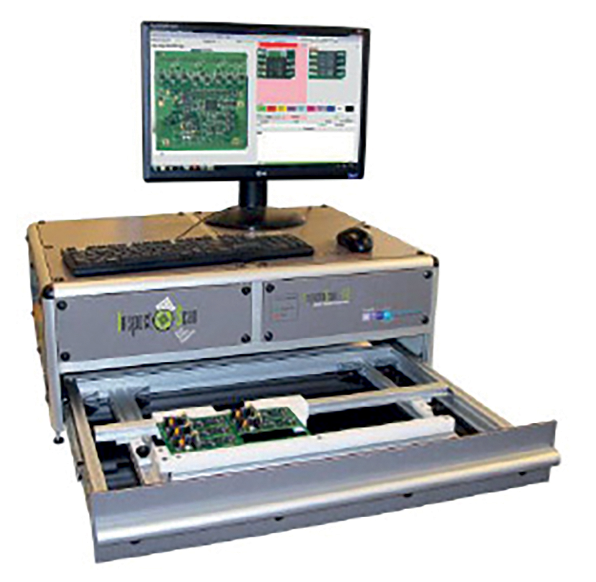
InspectoScan-S-A3 for the SMD Environment
Specifications
Benefits
Why InspectionScan-S
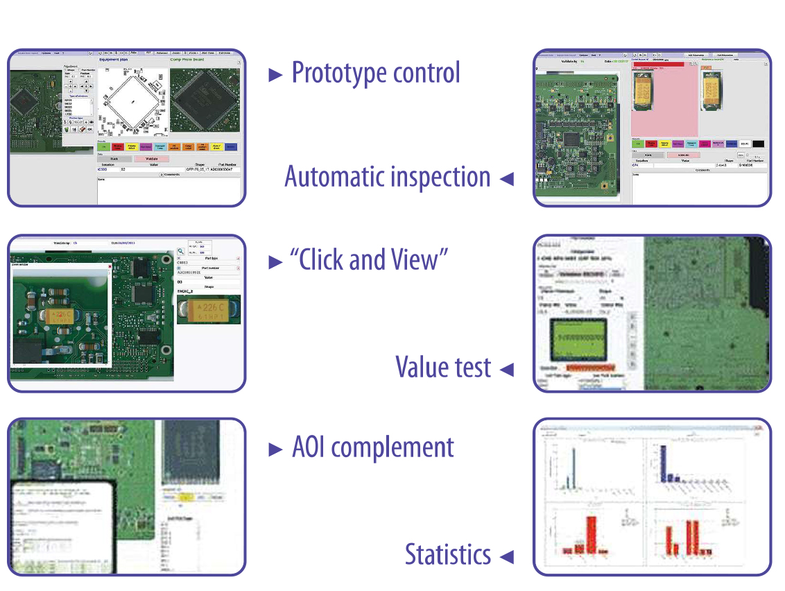
Quality Control: Prototype/First-Article Inspection/ Automated inspection for small &medium series
Improving end os line process yields and maximizing line UP time is the gola for every SMT Process Engineer. First Article inspection after set up and programming a placement machine is critical, checking the BOM and layout drawing against the first board assembled. Manual inspection on a complex board can take hours and is open to operation fatigue and errors. Using an AOI machine usually requires a trained operator and is an inefficient use of resources.
InspectoScan has been developed by SMT line engineers for SMT line engineers to effortlessly inspect first off assemblies.
Based on a professional high resolution (dpi) line scanner the system can recognise board edges or fiducials (auto align) and this automatically aligns with the centroid CAD data from any pick&place format plus the ability to additionally overlay a board map/plan.
The operator, who requires no programming skills, simply steps through the placement program checking off each part and storing a default image (zoom adjustable) at each position. The CAD data can provide part type, part reference, part size and positional location(s), the inspecting operator can firther add polarity check marks plus a free text box to add specific comments. On completion of the cycle a "golden reference board" has been created. The reference board and captured images can then be used to compare with other boards produced in the same or future batches; there is an option to add "alternative" images in the even of part type changes. At the end of each inspection cycle a report is generated that can be saved/printed (PDF) for build records and repair.
Automated Optical Inspection
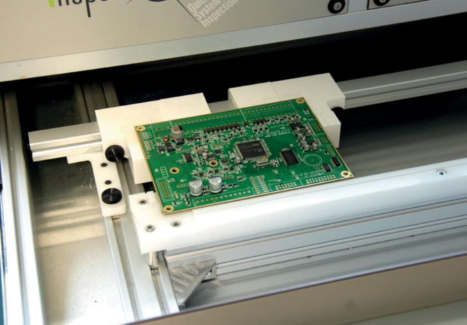
After location board on supporting edge clamps three fiducials automatically align software and a comparison is made between this inspected board and the golden reference board. The screen display highlights any errors graded Red to Green allowing the operator to quickly qualify any errors identified.
 |
 |